Graphical modeling of building plans (Quam 5.3)
To model a building plan with graphical tools, open the corresponding element and proceed as follows:
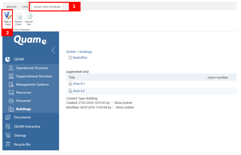
Open the |QUAM Visio Modeler tab (1).

If you want to create a drawing or make adjustments to an existing drawing, click the |Edit button in Visio (2) to open the drawing area in Microsoft Visio.
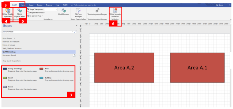
In Visio, open the |QUAM (3) tab in the upper navigation menu. Here you will find the following important functions:
- Save QUAM objects (4): The Visio drawing is saved in the database. Model objects are created, changed or deleted.
- Load QUAM objects (5): Existing model objects are imported from the database into the drawing.
- Close QUAM Modeler (6): Visio is closed. Unsaved data will be lost.

To import already created objects onto the drawing sheet, click on |QUAM Load objects. The individual objects now appear in the middle of the drawing sheet. To display them accordingly, however, you should rearrange and arrange the shapes. Proceed as described in chapter Layout adjustments of Visio process drawings (Quam 5.3).
To the left of the modeling area is the template with the available building shapes (7). To model the building plan, drag & drop the desired shapes onto the drawing area and arrange them accordingly.
Helpful tips and tricks can be found in chapter Tips for modeling with Visio (Quam 5.3).
It is possible to integrate pictures of building plans into the drawing area and to design these pictures interactively with transparent shapes. Read more about this in chapter Inserting Images - Transparent Shapes (Quam 5.3).
To graphically add information to newly created building plans, proceed as described in chapter Editing and linking elements (Quam 5.3).

